
001.Arduino UNO R3
2026-08-31 発掘されたマイコンボード
概要
- WindowsPCにつなぐぜ
- Lチカやるぜ!
- LCDと温度センサーつなぐぜ
Arduino UNO R3
イタリアで始まった、電子工作プラットフォームとそのハード・ソフトの統合環境を指す。オープンソースハードウエアという、仕様が公開されていて自由にこれを作成できる。
ドキュメント:UNO R3
現在はR4になっていたり他にもバリエーションがある。
手元にあるモノはおそらくhttps://elegoo.comで販売されていたELEGOO UNO R3 Project The Most Complete Starter Kitに含まれていたものだと思う。
このボードにはEthernetのコネクタが無くSSHで入って操作、みたいなことはできない。
USBでPCに接続、Adruino IDE からプログラムを書き込んで実行させる。
Arduino IDEはこちら https://www.arduino.cc/en/software/ からダウンロードしてインストール。
次にボード付属のUSBケーブルでPCとボードを接続する。Arduino IDEはボードを接続してから起動する。
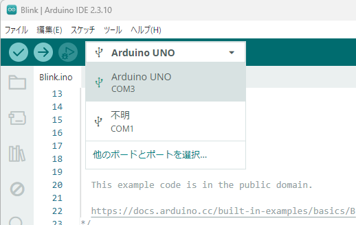
Arduino IDEのボード選択で「Arduino UNO」を選択。COMポートは環境依存かと。この例だとCOM3ポートに Arduino UNO R3 が接続されている。
本体Lチカ
多分ケーブルをつないだ直後から本体のLEDが点滅を始めていると思う。このプログラムが事前に書き込まれていたと思われる。
スケッチ例 の 01.Basic にある Blink はこれ。
この環境ではコードをスケッチと呼ぶ模様。
- Blink.ino
/*
  Blink

  Turns an LED on for one second, then off for one second, repeatedly.

  This example code is in the public domain.

  https://docs.arduino.cc/built-in-examples/basics/Blink/
*/

// the setup function runs once when you press reset or power the board
void setup() {
  // initialize digital pin LED_BUILTIN as an output.
  pinMode(LED_BUILTIN, OUTPUT);
}

// the loop function runs over and over again forever
void loop() {
  digitalWrite(LED_BUILTIN, HIGH);  // change state of the LED by setting the pin to the HIGH voltage level
  delay(1000);                      // wait for a second
  digitalWrite(LED_BUILTIN, LOW);   // change state of the LED by setting the pin to the LOW voltage level
  delay(1000);                      // wait for a second
}
LCDと温度センサーをつなぐ
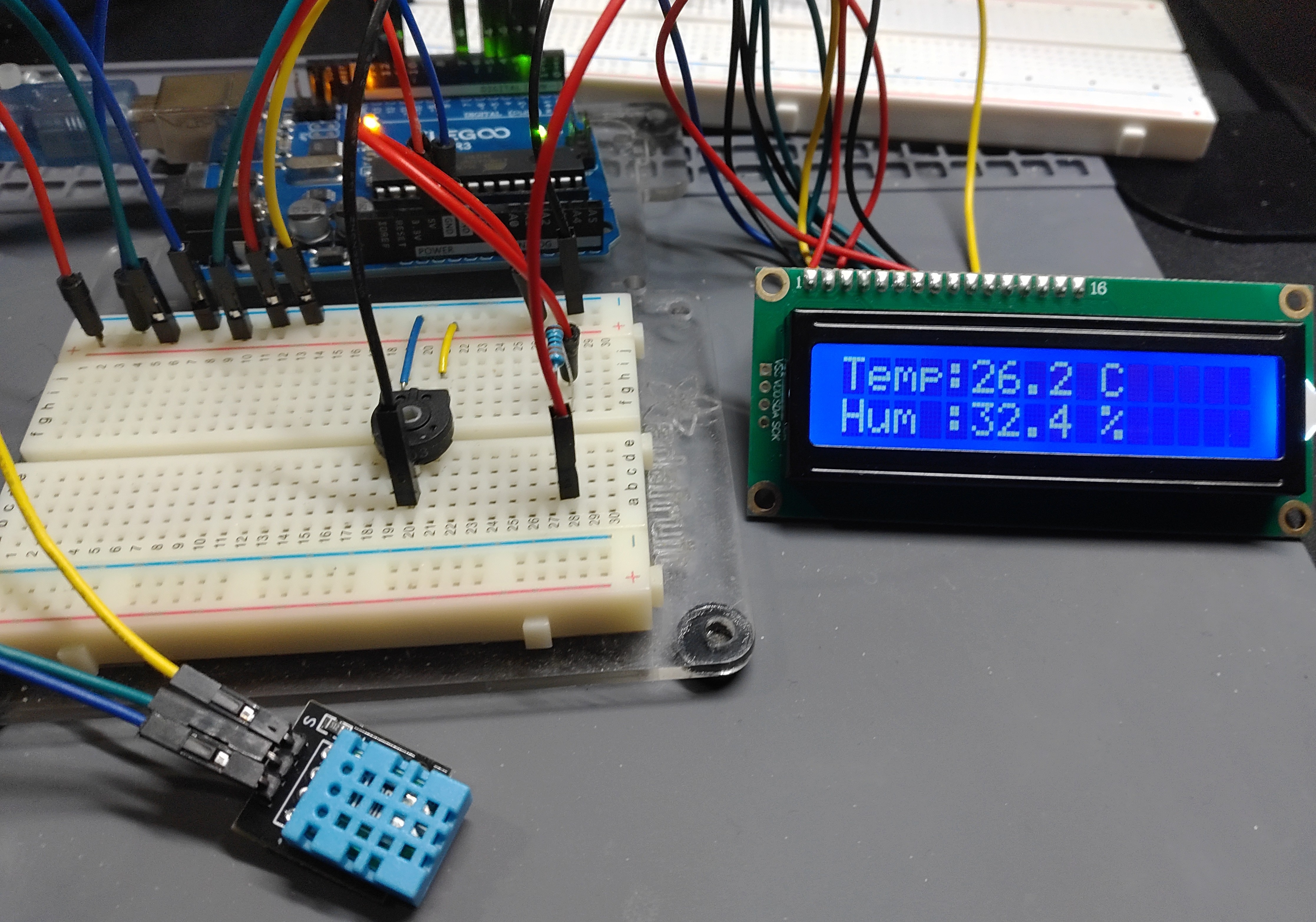
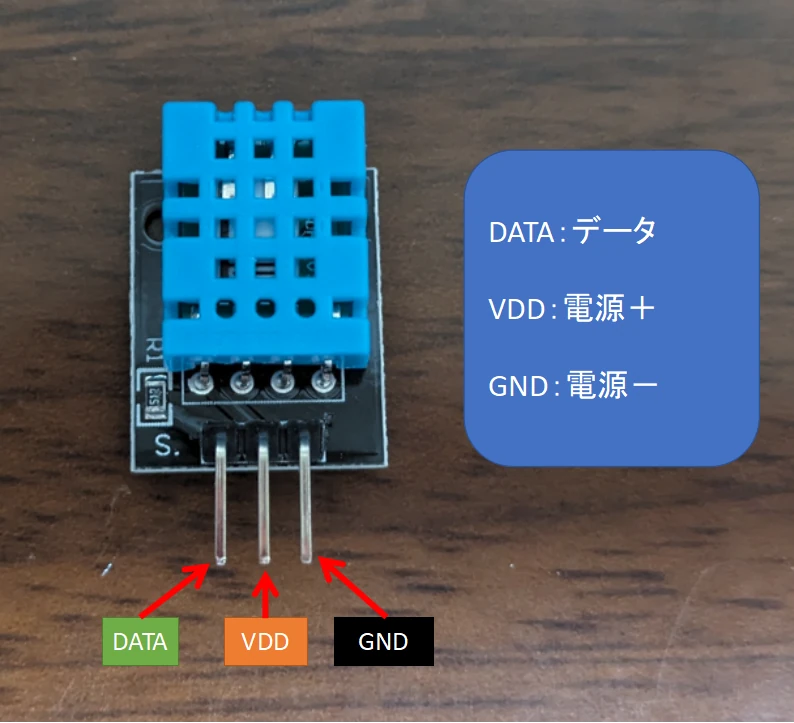
ArduinoはBBBの時と異なり5VをPINに直接入れられる。ついでにデジタル温湿度センサーモジュールDHT11も接続してLCDに数値を表示させてみる。
引用:Arduinoで温湿度センサDHT11を使ってI2C通信でLCDに値を表示!ビジュアルプログラミングLesson17
適宜必要なライブラリのインストール実施。
- LCDandTemputure.ino
#include <LiquidCrystal.h>
#include <DHT.h>

#define DHTPIN  7
#define DHTTYPE DHT11

LiquidCrystal lcd(12, 11, 5, 4, 3, 2);
DHT dht(DHTPIN, DHTTYPE);

// 部屋の湿度計に合わせた補正値
float adj = 0.675;

void setup()
{
    lcd.begin(16, 2);
    dht.begin();
    lcd.print("DHT11 starting");
    delay(2000);
    lcd.clear();
}

void loop()
{
    float hum  = dht.readHumidity();
    float temp = dht.readTemperature();

    if (isnan(hum) || isnan(temp)) {
        lcd.setCursor(0, 0);
        lcd.print("Sensor Error!   ");
        lcd.setCursor(0, 1);
        lcd.print("                ");
        delay(2000);
        return;
    }

    lcd.setCursor(0, 0);
    lcd.print("Temp:");
    lcd.print(temp, 1);
    lcd.print(" C   ");

    lcd.setCursor(0, 1);
    lcd.print("Hum :");
    lcd.print(hum * adj, 1);
    lcd.print(" %   ");

    delay(2000);
}
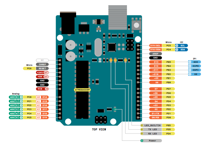
ピンアサインはこれ。
引用:UNO R3 Pinout(PDF)
ジャンパー線で配線。LCD側のPIN15(A),16(K)はバックライトLEDのもの。念のため330Ωの抵抗を通して接続している。
| Arduino 側 | パーツ側 |
|---|---|
| PD7 | DHT11 DATA(相互通信のライン) |
| PD5~PD2 | LCD1602A D7~D4 |
| PD12,PD11 | LCD1602A RS,E |
| +5V | LCD1602A VO(可変抵抗で調整) |
| +5V,GND | LCD1602A A(330Ωの抵抗経由),K |
| +5V,GND | DHT11 VCC,GND LCD1602A VDD,VSS |
適宜必要なライブラリを導入してスケッチをコンパイルしArduinoへ書き込む。
配線が正しければ写真の様にセンサーの数値を読み出してLCDに表示する。
BBBの時には気にしていた電圧・電流を考えずそのままArduinoのPINへ接続できるのが素晴らしい。